3 Equilibrium
Moment of force
Sometimes the reaction to a force is not in the same line with the force and causes twisting. This twisting effect is called the moment of the force. Moment of the force depends on two parameters:
force × perpendicular distance between the force path and the point about which the moment is taken
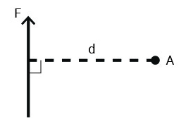
Figure 3-1: Moment of the force = force × perpendicular distance between the force path and the point about which the moment is taken
There is a sign convention for rotational forces. This sign convention does not relate to the direction of the force arrow but the direction of the rotation.
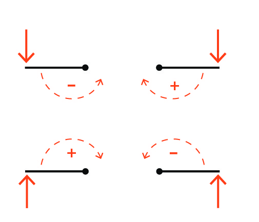
Figure 3-2: Sign convention for moment of the force
Newton’s First Law
An object at rest will remain at rest unless acted upon by an outside external net force.

Figure 3-3: Application of Newton’s first law in finding end reactions of simple beams
The following video (https://www.youtube.com/watch?v=6zXkYjmvLuI) explains the two conditions a body must satisfy to remain in equilibrium.
Video 3-1: Equilibrium of a body
You can see the rotational equilibrium in action in a balanced seesaw (lever) at your local playground. In the following image, the two individuals can determine the suitable length of the moment arm by adjusting their distances from the fulcrum to balance the seesaw.
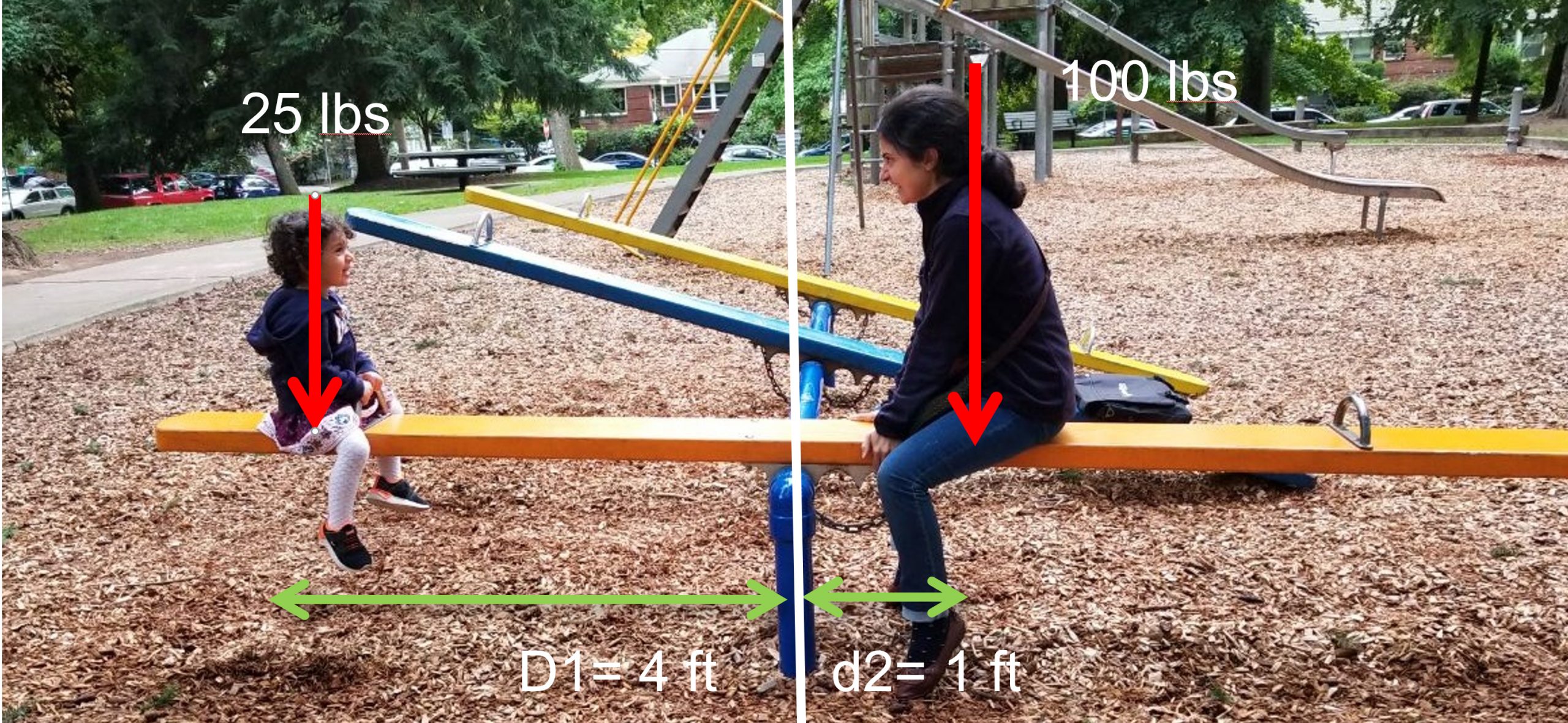
Figure 3-4: Equilibrium in a balanced seesaw
Rotational equilibrium requires: M1 + M2 = 0
M1 = F1 × d1 M1 = 25 × 4 = – 100
M2 = F2 × d2 M2 = 100 × 1 = +100
Stability against overturning
Watch the following video (https://www.youtube.com/watch?v=iDzp6xEAT2I) to learn how retaining walls work and how they resist sliding and overturning. This is similar to how the building as a whole needs to resist the hydrostatic and wind loads mentioned in Chapter 1.
Video 3-2: Stability of retaining walls
Resisting gravity must be greater than the overturning moment: MR> MO
Example: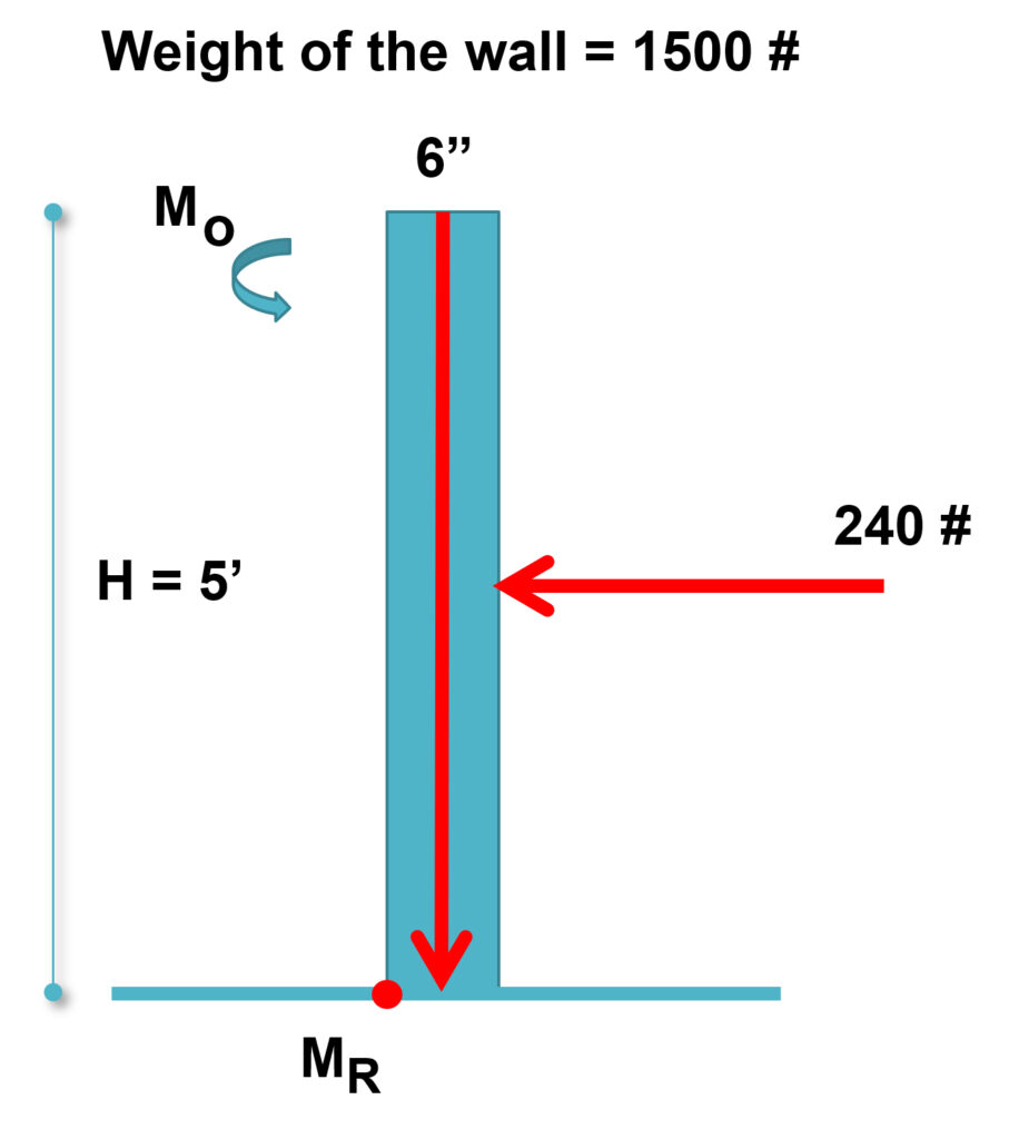
A concrete wall with a density of 150 pcf is expected to retain a mass of soil on one side. The distributed lateral load affecting the wall is equivalent to a point load of the soil at 24 psf. Study the wall stability against overturning and see if the wall stands the lateral load.
From the weight of the concrete wall:
MR = F x d = 1500 × (3/12) = 375 lbs-ft
From the soil:
Mo = F x d = 240 × 2.5’ = – 600
Thus, the wall falls over!
Archimedes’ principle of the lever
Archimedes’ principle of the lever indicates that two forces will balance at distances reciprocally proportional to their magnitudes.
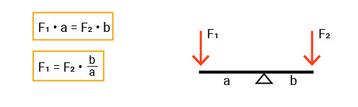
Figure 3-5: Archimedes’ principle of the lever
“Give me a place to stand, and I shall move the Earth.” To learn more about Archimedes’ idea and the amazing implications and uses of the lever, watch the following video:
Video 3-3: How levers work (https://www.youtube.com/watch?v=YlYEi0PgG1g)
Archimedes’ principle can be applied to determine the end reactions of beams at their supports. It also indicates that the support located nearer to the point load will bear a larger portion of the load and exert a greater vertical reaction force. In Figure 3-6, R2 will be greater than R1 because it is closer to point load P.
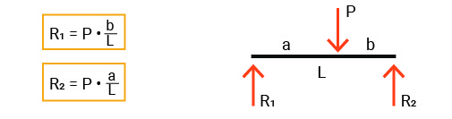
Figure 3-6: Application of Archimedes’ principle of the lever in finding end reactions in simple beams.
Determination of the end reactions in simple beams
There can be three reaction vectors in simple beams upon the support conditions: horizontal, vertical, and rotational. A roller support provides only a vertical reaction, allowing free movement in the horizontal and rotational directions. A hinge (or pinned) support resists both horizontal and vertical forces while allowing rotation. A fixed (or rigid) support resists movement in all three directions—horizontal, vertical, and rotational—providing reactions for each.
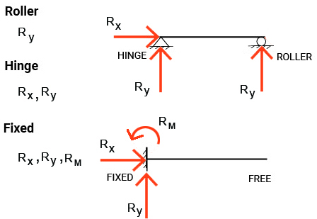
Figure 3-7: Reactions in beams with different support conditions

Figure 3-8: Hinged (pinned) connections in the structure of the Renault Center in Britain

Figure 3-9: Hinged (pinned) connections in the structure of the George Pompidou Center
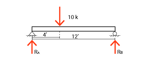
Example 1
Using Newton’s first law or Archimedes principle of the lever, we can study the following simple beam and find the shares of the two end supports of reacting to the point load P applied to the beam.
To proceed:
- Label components of reactions. Consider the support condition and see if you should include vertical, horizontal, and rotational reactions.
- Use the summation of moments about A to find RB.
- Use the summation of moments about B to find RA OR Find RA load by summing vertical forces.
Σ Fx = 0 All horizontal forces must balance out to zero. No horizontal force!
Σ FY = 0 All vertical forces must balance out to zero.
RA+RB -10=0
RA+RB=10
Σ M1 = 0 All rotational forces must balance out to zero.
P × a – RB×L+RA×0 = 0
10 × 4 – RB×12+0= 0
RB = 40/12 =3.33 kip
RA = 10 – 3.33 = 6.67 kip
Example 2
Find the end reactions at the supports of the simple beam shown below:
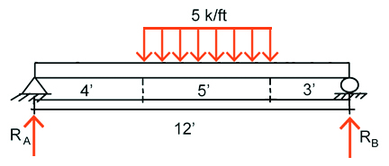
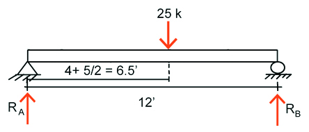
The effect of the distributed load applied to the beam can be studied by replacing it with its equivalent point load shown below:
Σ Fx = 0 All horizontal forces must balance out to zero.
No horizontal force!
Σ FY = 0 All vertical forces must balance out to zero.
P= w × d = 5 × 5 = 25 k
RA+RB -25 = 0
RA+RB = 25
Σ M_A = 0 All rotational forces must balance out to zero.
25 × 6.5 – RB×12+RA×0 = 0
RB = 162.5 / 12 = 13.54 k
RA = 25 – 13.54 = 11.46 k
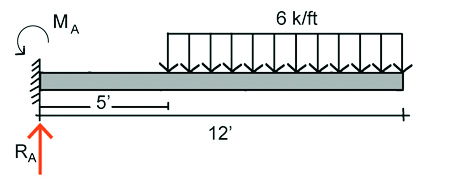
Example 3
Find the end reactions at the support of the cantilever beam shown below:
Σ Fx = 0
Σ FY = 0
The length of the beam loaded uniformly = 12-5 = 7
P= w × d = 6 × 7 = 42 kips
The moment arm of the uniformly distributed load w = 5 + 7/2 = 8.5
RA-42=0
RA=42
Σ MA = 0 All rotational forces must balance out to zero.
42 × 8.5 – MA = 0
MA = 357 kips. ft
Computational analysis of a simple beam using Karamba 3D
You can use computational simulation tools to analyze a simple beam with different support conditions and load combinations. Video 3-4 demonstrates how to use Karamba 3D to analyze a simple beam held by a hinge and a roller support. In this video. You will see how you can define the geometry of the beam, support types, and the load combination. Then, you will learn how to find the numeric values of the support reactions and visualize the beam’s displacement under a given load. If you are unfamiliar with the Grasshopper interface and would like to briefly learn how to navigate, watch Video 3-5. The video introduces different features and components of the Grasshopper interface.
Video 3-4: Analyzing a simple beam on a hinge and a roller using Karamba 3D
Video 3-5: Brief introduction to the Grasshopper interface
Topics for critical thinking
- Use a beam calculator interface to check your calculations when solving the reactions at the supports of a beam.
