8 Cross-sectional Properties
Designing Structural elements requires knowledge of applied external loads and internal reactions, material strengths, and cross-sectional properties. The geometrical properties of a structural element are critical in keeping axial, shear, and bending stresses within allowable limits and moderating the amount of deflection. The following demonstrations show how the shape of the cross-sections affects their stiffness.
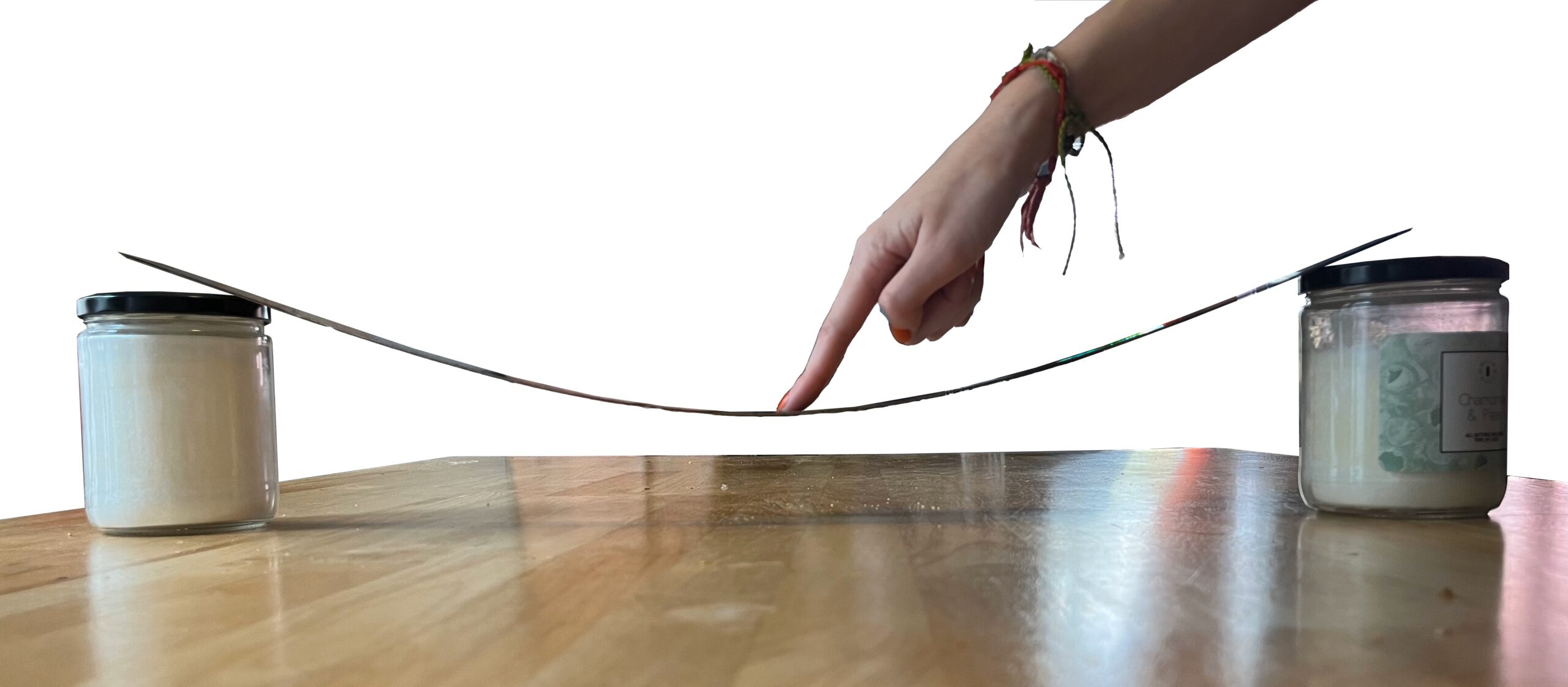
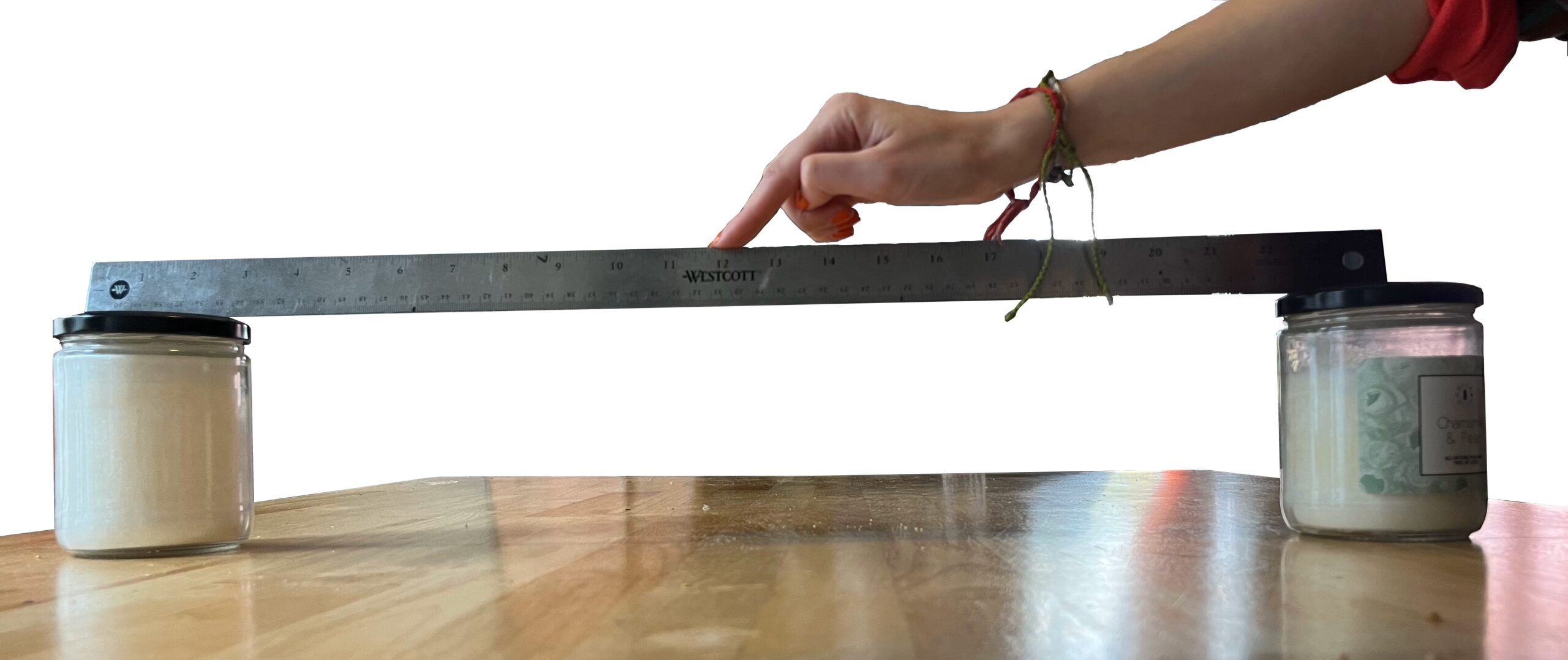
Figure 8-1: Relation between the cross-sectional depth (rise) of a beam and its stiffness
Chapter 7 discussed that “area” is one of the cross-sectional properties, which is important to reduce the amount of stress in beams and columns. This chapter focuses on the shape of the cross-sectional area and its distribution about the neutral axis of beams. In the following, some cross-sectional properties that will be necessary to calculate beams and columns are introduced.
Center of gravity
The center of gravity of a body is the point about which the mass of the body is balanced or the point through which the weight of the body acts. When the density of a body is uniform throughout, the center of gravity and the centroid (geometric center) of the body are at the same point.
- The centroid of a rectangle is defined as the center point where all the diagonals intersect each other.
- The centroid of a triangle is the point where the three medians of the triangle meet.

Figure 8-2: The center of gravity of some basic geometrical shapes
Video 8-1: Neutral axis in a beam (https://www.youtube.com/watch?v=BthnS6LJt8s&t=1s)
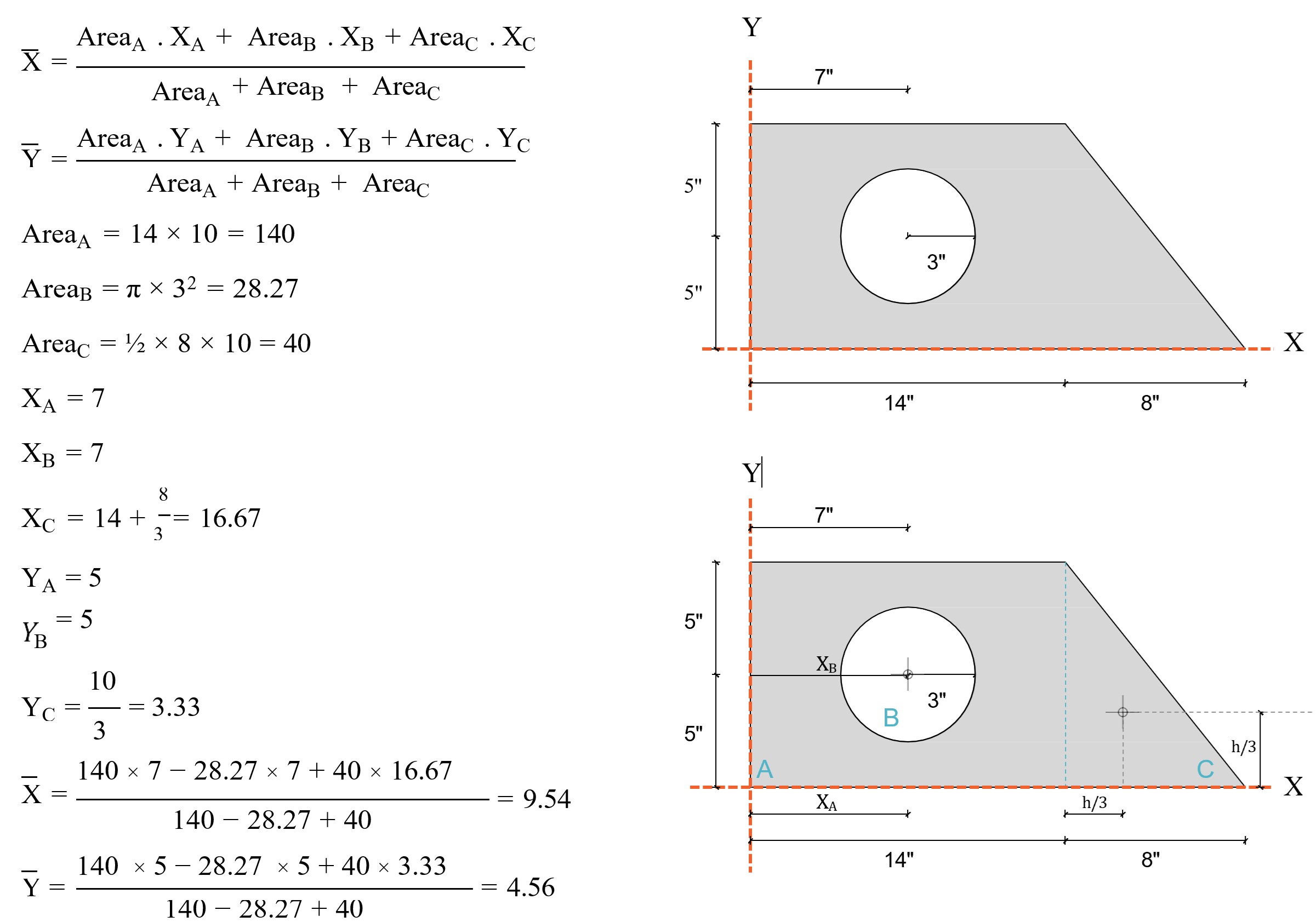
You can use the following equation to find the center of Gravity of a compound shape:
[latex]\bar{X}= \frac{\sum ({Area \times d_x})}{\sum{Area}}[/latex]
[latex]\bar{Y} = \frac{\sum( {Area \times d_y})}{\sum{Area}}[/latex]
Example
1st Moment of Area
Video 8-2: A demonstration of the moment of areas of two rods (https://www.youtube.com/watch?v=m9weJfoW5J0)
By definition, the tendency of an area alone to rotate about an axis in the plane of that area.
Q = A[latex]\bar{x}[/latex]
At the Neutral/Centroid axis:
A1 x1 = A2x2
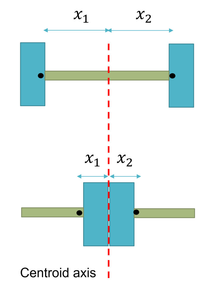
Figure 8-3: The difference of 1st moment of area in two beams with different cross sections
2nd Moment of Area/Inertia
By definition, the 2nd moment of area is the distance of force distribution from the neutral axis. The 2nd moment of area is a geometric property that describes how the area of a cross-section is distributed around the neutral axis, essentially measuring how resistant a shape is to bending forces and deflection. The 2nd moment of area involved the first moment of area multiply by a second moment arm. The second moment arm is the distance between the centroid of the force distribution and the neutral axis.
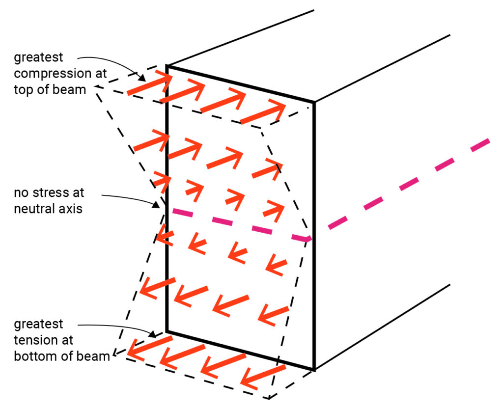
Figure 8-4: The pattern of force distribution in relation to the distance from the neutral axis
The second moment of area of a beam with a rectangular section can be calculated using the following equation:
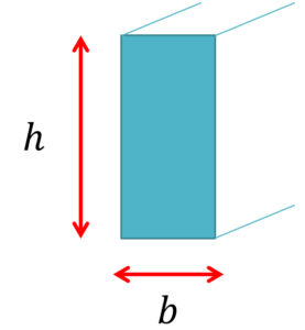
Ix = [latex]\frac{bh^3}{12}[/latex]
Where:
Ix = Second moment of area
h = depth of the beam
b = with of the beam

Figure 8-5: The second moment of areas for a few regular shapes
Section Modulus
By definition, the section modulus (Sx) of a beam with a symmetric section equals its second moment of area divided by half its depth at the extreme fiber.
Sx = [latex]\frac{I_x}{c}[/latex]
Where:
Sx = Section modulus
Ix = Second moment of area
c= h/2 at extreme fibers of a symmetric section
h = depth of the beam
The section modulus will help determine the cross-section shape of a beam as discussed in the Chapter 9.
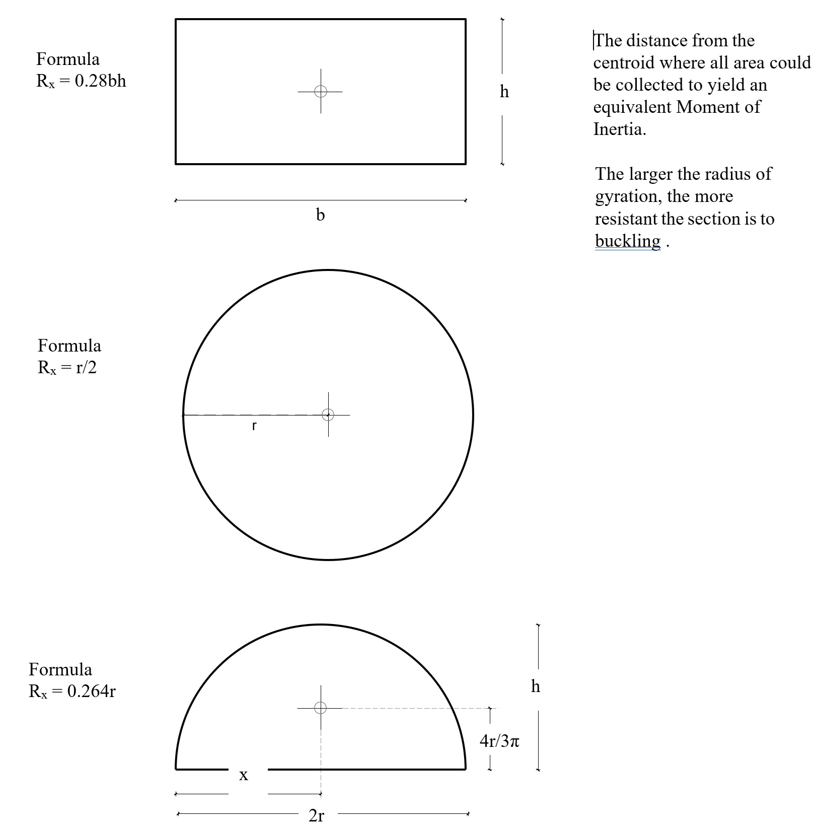
Radius of Gyration
Radius of gyration is a geometric property of a cross-section that describes how the area is distributed about an axis.
It can be thought of as the distance from the centroid at which the entire cross-sectional area could be concentrated without changing the section’s moment of inertia.
Mathematically, it is defined as:
\( r = \sqrt{\frac{I}{A}} \)
where I is the moment of inertia and A is the cross-sectional area.
The larger the radius of gyration, the more the material is spread away from the centroid, and the greater the member’s resistance to buckling under compression.
This is why hollow tubes, wide-flange shapes, and other sections with material placed farther from the center tend to perform better against buckling than solid bars of the same area.
In design terms:
-
Area constant, r increases → Buckling resistance increases.
-
Small r (material close to the centroid) → Member is slender and more prone to buckling.
Geometrical properties of steel beam cross-sections
Tables of design dimensions, detailing dimensions, axial flexure, strong-axis flexure, and weak-axis flexure of steel beams are provided in the Steel Construction Manual published by the American Institute of Steel Construction (AISC). You may find the cross-sectional area (A), depth of the beam (d), Ix, and Sx.
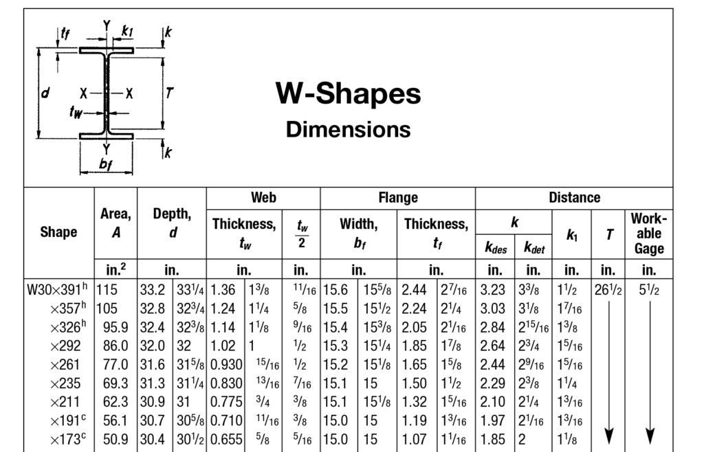
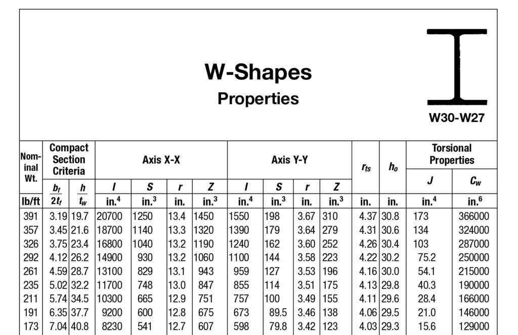
Figure 8-5: Example of steel profiles listed in Steel Construction Manual [15]
